

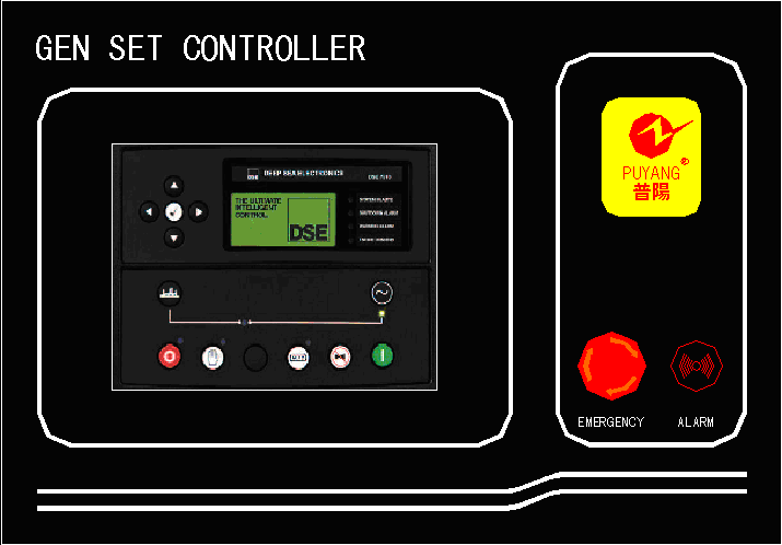

Figure 2.1 PK01-1 control screen
2.2 PK01-3 (HGM1750 ordinary control panel)
1> manual operation function: including unit start-up, shutdown, emergency stop button, high and low speed control;
2> analog instrument display: the display items include three phase voltage, three phase current and frequency;
3> liquid crystal display content:
|
Power generation voltage V |
Generation frequency Hz |
|
Engine temperature C |
Oil pressure kPa |
|
Speed rpm |
Cumulative running time H |
|
Battery voltage V |
Fuel level% |
1> protection:
|
warning |
Alarm and stop |
|
Battery voltage exorbitant warning |
Low oil pressure warning, shutdown |
|
Low fuel level warning |
Exorbitant warning and shutdown of power generation voltage |
|
Downtime failure |
Overspeed alarm stop |
|
Emergency shutdown |
High temperature warning, shutdown |
|
Failure of charging |
Over frequency alarm stop |
|
Battery voltage low warning |
|

Figure 2.2 PK01-3 control screen
3. automatic control panel
3.1 PK02-1 (HGM7210 control panel) function

Figure 3.1 PK02-1 control screen
1> manual and automatic operation function;
2> city power loss automatic start;
3> LCD LCD display in Chinese or English;
4> optional function: remote monitoring function. Communication with PC equipped with monitoring software can start and stop generator units by remote PC operation and monitor the operation state of generating units.
1> warning warning project:
|
Overspeed warning |
Less speed warning |
|
Speed signal loss warning |
Power generation over frequency warning |
|
Power generation warning |
Overvoltage warning for power generation |
|
Undervoltage warning of power generation |
Power generation overflow warning |
|
Shutdown failure warning |
Charging failure warning |
|
Battery overvoltage warning |
Battery undervoltage warning |
|
Maintenance time to warning |
Reverse power warning |
|
Overpower warning |
ECU warning |
|
Power generation warning |
Generating reverse phase sequence warning |
|
Switch conversion failure warning |
Temperature sensor open circuit warning |
|
High temperature warning |
Low temperature warning |
|
Oil pressure sensor opening warning |
Low oil pressure warning |
|
Open circuit warning for liquid level sensor |
Low level warning |
|
Programmable sensor open warning |
GSM communication failure warning |
2>Shutdown alarm project
|
Emergency shutdown alarm |
Overspeed alarm stop |
|
Low speed alarm stop |
Speed signal loss alarm stop |
|
Over frequency alarm stop |
Under frequency alarm stop |
|
Power generation overvoltage alarm stop |
Power generation undervoltage alarm shutdown |
|
Start failure alarm stop |
Power generation overcurrent alarm stop |
|
Maintenance time to alarm stop |
ECU alarm stop |
|
ECU communication failure alarm stop |
Reverse power alarm |
|
Overpower alarm stop |
Open circuit of temperature sensor |
|
High temperature alarm stop |
Open circuit of oil pressure sensor |
|
Low oil pressure alarm stop |
Opening of liquid level sensor |
|
Open circuit of programmable sensor |
|
3> Shutdown alarm
|
Overcurrent shut-down |
Maintenance time to shutting down |
|
Reverse power tripping |
Overpower tripping |
|
Shut-down |
|
4> No stop alarm for tripping
|
Overcurrent tripping |
Reverse power tripping |
|
Overpower tripping |
Input gate tripping |
4.Parallel machine control panel

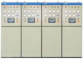
Figure 4.1 PK02-B+PK06 automation and screen Figure 4.2 PK07 cabinet type and cabinet
4.1 parallel machine control panel (cabinet) function
In order to improve the reliability of diesel power station, reduce the running cost of low load, or consider the need for expansion of diesel power station, the parallel operation of multiple units can be considered.
Common forms of parallel operation control system are backpack machine and cabinet type parallel machine.
The knapsack automatic parallel system integrates the components of the starting system into a single unit. The units below 400KW do not need separate switchgear cabinets. They are mainly equipped with standard unit plus backpack type control panel plus side mounted electric closing switch.
The cabinet automatic and parallel cabinet can automatically accomplish the operation of unit startup, parallel operation, load distribution, load transfer, downtime and so on, and all processes can be operated manually. The main configuration is to configure an automatic parallel switch cabinet for each standard unit.
The machine control panel is suitable for the manual / automatic parallel system of up to 32 units with same capacity or different capacity. It can realize the automatic starting / stopping, data measurement, alarm protection and "three remote" function of the generator set. The controller adopts large screen liquid crystal display (LCD). It can choose the operation interface between Chinese and English, simple operation and reliable operation. With the functions of controlling GOV and AVR, it can automatically synchronize and load evenly, and connect the generator set equipped with DSE7510 automatic parallel control panel.
There are many modes of operation in automatic state: running without load, running on load and running in parallel with demand.
With parallel / demultiplexing, load soft transfer function;
It has the function of weekly / monthly cycle start / downtime, and can also be loaded with (parallel) / no load test machine.
Accurate measurement and display function: real-time monitoring of diesel generator's electrical parameters, water temperature, oil pressure and oil level;
Control and protection function: realizing automatic start up, shutdown, parallel, synchronous detection, load sharing and alarm protection functions of generating units.
Have the maintenance / maintenance time of the unit to warn / stop function.
It can save 99 sets of historical records and query the records at the same time. At the same time, the fault status is displayed on LCD.
The RS485/232C communication interface adopts the MODBUS communication protocol, which can realize the "four remotely" function of the generating set.
4.2 controller page display function introduction
4.2.1 power generation project:
A) three-phase phase voltage Ua, Ub, Uc unit: V
B) three-phase line voltage Uab, Ubc, Uca unit: V
C) three phase current Ia, Ib, Ic unit: A
D) frequency F unit: Hz
E) phase divided active power PA, PB, PC unit: kW
F) total active power P unit of total phase: kW
G) phase splitting reactive power RA, RB, RC unit: kvar
H) total reactive power P total unit: kvar
I) split phase in power SA, SB, SC unit: kVA
J) mutual view in the total power S unit of total power: KVA
K) phase separation power factor PF1, PF2, PF3
L) average power factor P average
M) accumulative active power unit: kWh
N) accumulative reactive power unit: kVarh
O) accumulated as a unit of power: kVA
P) detection of phase and phase angle of three-phase voltage
4.2.2 bus power item:
A) three-phase phase voltage Ua, Ub, Uc unit: V
B) three-phase line voltage Uab, Ubc, Uca unit: V
C) frequency F unit: Hz
D) detection of phase and phase angle of three-phase voltage
4.2.3 synchronization parameter project:
A) detection of voltage difference between power generation and busbar
B) detection of difference between power generation and bus row angle
C) detection of frequency difference between power generation and busbar
4.2.4 conditions for generating abnormal power generation:
A) high voltage; b) voltage is too low; c) frequency is too high; d) frequency is too low; E) lack phase; F) inverse phase sequence; g) power loss.
4.3 controller alarm and protection function items:
The 4.3.1 warning is a non emergency alarm state, which does not affect the normal operation of the unit. When the alarm occurs, the unit will not stop, and when the condition of the alarm does not exist, the warning will disappear automatically. The warning is as follows:
Power generation overflow warning; shutdown failure warning; low fuel level warning; charging failure warning; speed signal loss warning; incipient battery undervoltage warning; starter overvoltage warning; power generation failure auxiliary input warning; maintenance time to; synchronization failure; generation phase sequence error; busbar phase sequence error; MSC data error; MSC Few modules; ECU warning alarm; load current imbalance; high temperature warning; low temperature warning; low oil pressure warning; overspeed warning; underspeed warning; generation overfrequency warnings; generation Underfrequency warnings; generation overvoltage warnings; power generation undervoltage warnings; demagnetization warnings.
4.3.2 outage alarm
The downtime alarm volume needs manual reset to remove, and will not disappear automatically. When the downtime alarm occurs, the unit will be shut down.
Emergency shutdown alarm; high temperature alarm stop; low oil pressure alarm stop; power generation overspeed alarm stop; power generation underspeed alarm stop; power generation over frequency alarm stop; power generation over frequency alarm stop; power generation overvoltage alarm stop; power generation undervoltage alarm stop; power generation over current alarm stop; power generation over current alarm stop; start failure; start failure. The alarm is stopped, the oil pressure sensor opens the alarm input port to stop alarm, the CAN bus fails to stop, the load current is unbalanced, and the ECU alarm stops.
4.3.3 shut-down
When the controller detects the electrical trip signal, the controller immediately disconnects the power generation relay relay signal to disconnect the load, and then stops the generator after high speed heat dissipation.
Power generation overcurrent trip alarm; reverse power trip alarm; loss of excitation trip alarm; load current imbalance input tripping alarm; MSC error; MSC module less.
Schematic diagram of 4.4 parallel machine control panel